

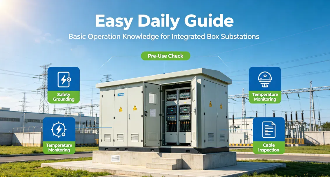
 A pad-mounted substation (commonly referred to as a "compact substation") is a compact, factory-assembled power distribution facility that integrates high-voltage switchgear, distribution transformers, and low-voltage distribution devices within a fully enclosed steel enclosure. It is widely used in urban residential areas, industrial parks, highways, and temporary construction sites. The core of daily operation and maintenance can be summarized as: moisture-proof, dust-proof, overheat-proof, and animal-proof.
I. Structural Composition – "Three Compartments"
A compact substation is typically divided into three isolated compartments:
1. High-Voltage Compartment: Contains the high-voltage incoming cabinet, outgoing cabinet, load switches, or circuit breakers, responsible for power intake and protection.
2. Transformer Compartment: The core of the substation, usually housing an oil-immersed or dry-type transformer for voltage conversion.
3. Low-Voltage Compartment: Contains the low-voltage main switch, outgoing switches, reactive power compensation devices, etc., responsible for power distribution.
⚠️ Proper fire isolation and ventilation/heat dissipation design should be provided between the three compartments.
II. Daily Inspection – "Four Key Actions"
1. Look
o Appearance: Check for deformation, rust, tilting; ensure cabinet doors are tightly closed; inspect rainproof eaves.
o Oil Level (for oil-immersed transformers): Ensure the oil level gauge is within the normal range (1/2–2/3), and check for oil leakage traces.
o Instruments: Verify normal readings of voltage, current, and temperature; check if the reactive power compensation controller shows any alarms.
o Indicator Lights: Ensure all circuit running indicators are lit normally.
2. Listen
o Normal: A steady, uniform "hum" from the transformer.
o Abnormal: "Crackling" discharge sounds, "bubbling" boiling sounds, or irregular vibrations indicate possible partial discharge, overload, or mechanical looseness.
3. Smell
o Normal: No noticeable odor.
o Abnormal: Burning smell → insulation overheating; ozone smell → corona discharge or flashover; oily smell → transformer oil leakage.
4. Measure (Key Focus)
o Use an infrared thermometer to check:
§ Transformer enclosure temperature (top oil temperature for oil-immersed transformers generally should not exceed 85°C);
§ High/low-voltage cable joint temperature (temperature rise should not exceed 60K);
§ Inner wall temperature of the enclosure to assess heat dissipation performance.
o Check whether the temperature/humidity controller and exhaust fans start up automatically.
III. Environmental Management Essentials
· Foundation and Drainage: The substation foundation should be at least 300mm above ground level, with smooth drainage around it to prevent flooding from heavy rain.
· Ventilation and Heat Dissipation: Louvers and exhaust fans are installed on the top or sides of the enclosure. During hot summer periods, ensure fans are operating properly; poor cooling can cause transformer derating or even tripping.
· Animal Prevention: Cable entry/exit holes must be sealed tightly with fire-stop putty; rodent repellents or glue traps can be installed inside the cabinet. Animal-caused short circuits are a major cause of unplanned outages.
· Moisture and Condensation Control: During rainy or condensation seasons, check whether cabinet heaters are working properly to prevent insulation degradation and flashover.
IV. Operation and Safety Red Lines
1. Power-Off Sequence:
o First, open all low-voltage outgoing switches → then open the low-voltage main switch → finally open the high-voltage load switch or dropout fuse.
o Power-on sequence is the reverse: close high-voltage side first → then close the low-voltage main switch → finally close each outgoing switch.
2. Strictly prohibit opening/closing high-voltage disconnect switches under load (unless they have arc-extinguishing devices).
3. Before entering the substation for work:
o Confirm that the high-voltage side has been de-energized and grounding wires are attached;
o Use a voltage detector to verify no voltage at the high-voltage compartment and transformer side;
o At least two persons must be present – one to operate and one to supervise.
4. Warning Signs: The substation exterior should display warning placards such as "Danger – High Voltage – No Climbing"; fences or protective nets must be intact.
V. Common Faults and Emergency Handling
Fault Phenomenon | Possible Causes | Handling Suggestions |
|---|---|---|
Transformer temperature rises abnormally | Overload, cooling fan stopped, high ambient temperature, low oil level | Check load rate; troubleshoot fan issues; refill oil or plan load reduction; enhance ventilation. |
Low-voltage main switch trips | Short circuit on outgoing circuits, overload, leakage | Test-feed circuits segment by segment to locate the faulty circuit; re-close only after clearing the fault. |
High-voltage fuse blows (dropout type) | Internal short circuit in transformer, overload, lightning strike | Check transformer insulation resistance and DC resistance; do not blindly replace the fuse and re-energize before identifying the root cause. |
Severe condensation inside the cabinet | Heater failure, poor sealing, high humidity | Replace heater; check sealing strips; temporarily open cabinet doors for ventilation (with safety precautions). |
Sudden increase in noise | Voltage imbalance, loose core, asymmetric load | Measure three-phase voltage and current; check whether transformer mounting bolts are loose. |
VI. Recommended Maintenance Intervals
· Monthly: Visual inspection, clean cooling louvers, check heaters and fans.
· Quarterly: Infrared temperature measurement, inspect tightness of cable joints, clean dust inside the cabinet.
Annually (power-off maintenance): Tighten all busbar bolts; test insulation resistance; verify protection settings; replace aged sealing rings and desiccant (breather silica gel).